This circuit was originally included in my book Mechatronics for the Evil Genius (TAB 2006) to be part of the article Ionic Motor. See more about the Ionic Motor in this site.
Galvanometers are sensitive, electric current detectors. When the evil genius builds a galvanometer, he or she will also be able to identify some interesting mechatronic devices and perform experiments with alternative energy sources and photoelectric sensors.
The basic version of the galvanometer described here can detect currents as low as a few microamperes (mA), and with the aid of an electronic ampli- fier, even weaker currents can be detected. The high sensitivity achieved by using the additional circuit is perfect for projects like the following:
Building a lie detector
Identifying energy from experimental sources
Building a light/dark detector
The project uses only a few components, most obtained from common sources such as old appliances and home Objects, Which Will have no costs to the reader. Due the simplicity of the project, it is ideal for beginning evil geniuses, elementary students, and for teachers who want simple experiments to make their classes more interesting.
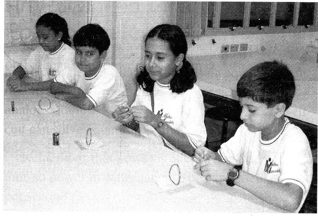
A cross theme found in this project was used by the classes at the school where the author teaches. Figure1 shows the young students building their galvanometers to perform some experiments to detect electric currents. Experiments can be designed with different levels of difficulty according to the grade level of the students.
Objectives
Although it can be great fun detecting currents with the galvanometer, some important objectives should be considered when mounting this galvanometer.
Readers can learn about the following themes:
How to detect electric currents
What Oesterd discovered about electric currents and magnetic fields
How to build alternative sOurces of energy
The operation principles of real galvanometers
The Project
The basic project is to build a sensitive galvanometer using only a small number of components. The project consists of creating a coil that involves a magnetic needle hung by a thin line. When an electric current passes across the coil, a magnetic field is created and its action moves the needle.
By the movement of the needle, the reader can evaluate the amount of current in the coil. It is possible to detect even very weak currents in the range of few microamperes or millionths of amperes. A current produced by two metallic plates inserted in a lemon is enough to move the needle of this sensitive detector.
How it Works
The Danish professor Hans Christian Oesterd discovered that electric currents can create magnetic fields.
In his experiment, he placed a metallic wire near a compass, as shown in Figure 2.
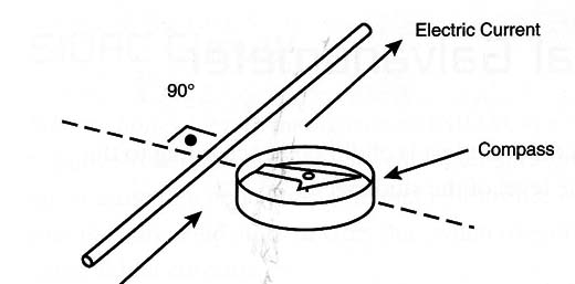
When the switch was closed, the electric current flowing across the wire created a magnetic field strong enough to displace the needle of the compass.
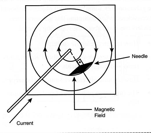
The needle moved, stopping in a' position parallel to the force lines of the magnetic field (i.e., perpendicular to the field), as shown in Figure 3.
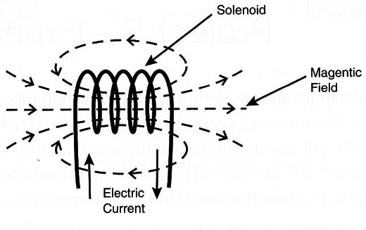
After this experiment, the researchers discovered that if the wire was wound into a coil, the magnetic field could be concentrated inside it, as shown in Figure 4.
As the reader can see, an electric current can move a needle to construct an electric current detector. This kind of instrument is called a galvanometer.
Modern analog galvanometers consist of moving coils placed between the poles of a magnet, as shown in Figure 5.
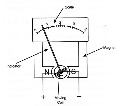
When the electric current flows across the coil, the magnetic field reacts with the field of the permanent magnet, creating a force that tends to rotate the coil.
The force and the displacement are proportional to the amount of current and therefore to the displacement of a pointer along a scale.
Our galvanometer is very simple in its basic version but can be upgraded according to the skills and imagination of the reader. Although the sensitivity of our galvanometer is high, by adding electronic circuits, the sensitivity can be increased to an even greater level. Currents of a few microamperes can be detected by our more sensitive galvanometer.
Building the Galvanometer
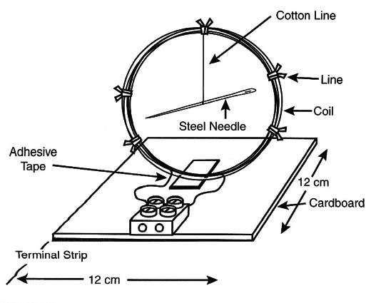
Figure 6 shows the plans to build the galvanometer. The coil is wound around any cylindrical object with a diameter between 7 and 10 cm. You can use any wire you have on hand. You can choose from common plastic-covered wire (between 22 and 26 gauge) or enameled wire (between 22 and 28 AWG). Don’t use very thin wires because they can,t hold the needle.

The number of turns in your coil will determine the sensitivity and the electrical characteristics of your galvanometer. l recommend using 20 to 50 turns, depending on the wire you choose. To keep the turns coiled tightly together, you can use a string or an adhesive band once you have finished Winding. The coil is then placed in a cardboard or wooden base. You can use glue or an adhesive band to secure it here.
Screws are used to connect the terminal strip that holds the coil to the external circuit. Remove the cover to connect the ends of the coil to the terminals.
The enameled wires need to be uncovered as well, because the small layer of enamel acts as an isolator.
Use a small pocketknife or Wire cutters (and adult supervision if necessary) to remove the wire cover.
The next step in mounting the galvanometer is to prepare the needle. First, find a needle with a length between 5 and 7 centimeters. Rub it against a magnet to magnetize it. Then tie one end of a length of string to the needle. Tie the other end of the string to the coil.
Then hang the needle inside the coil in equilibrium. The needle should be at the center of the coil and without touching it. Figure 7 shows the galvanometer ready to be tested and used.
5 to 15 meters of wire (see text)
1 needle - 5 to 7 cm long
1 piece of cardboard, 12 x 12 cm
1 terminal strip with screws
String, adhesive band, glue, etc.
Testing the Galvanometer
A simple circuit that allows you to determine the sensitivity of the galvanometer is shown in Figure 8.
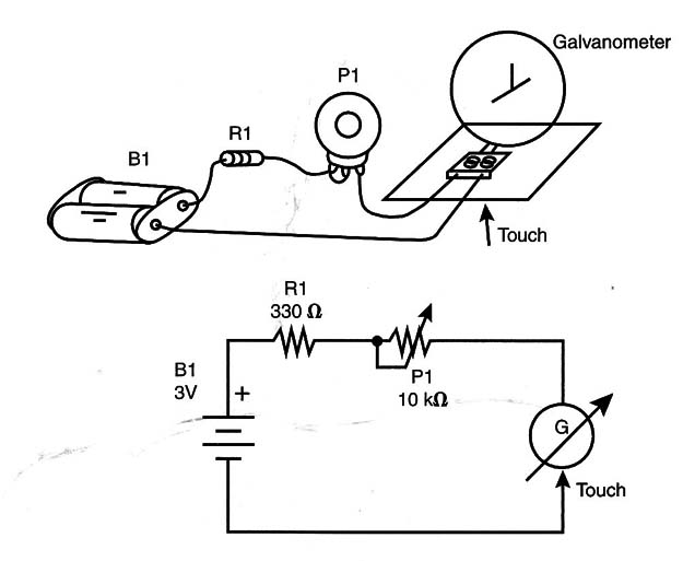
First, adjust the potentiometer for the maximum value of resistance. This means you will need to move the cursor all the way to the right. Using a 10 k ohm potentiometer, the probe current should be about 0.3 mA or 300 µA.
Touching the terminal with the wire from the battery holder, as indicated in the figure, observe whether the needle moves. If it moves, your galvanometer is sensitive enough to detect a current as low as 300 µA.
If not, move the cursor of your potentiometer a few degrees to the left-about 2/3 of the complete rotation. By doing this, the resistance will fall to about 7,000 ohm. The probe current is now something less than 0.5 mA or 500 µA. Repeat the test.
If the needle moves, your galvanometer has a sensitivity of about 0.5 mA. If not, reduce the resistance of the potentiometer a little more, increasing the test current.
Place the cursor to 1/3 of the complete resistance, which places it in the range of 3,500 Ω. Considering the tolerances of the components, you will have a probe current of about 1 mA. Repeat the test, and observe if the needle moves. If the answer is yes, the sensitivity of your galvanometer is 1 mA. If not, increase the current again.
Now closing the potentiometer to have a zero resistance, the only resistance in the circuit is R1.
With the 3-volt supply, the probe current will be 6 mA. Repeat the test. The needle must move now. If not, rebuild the unit, using more wire in the coil and verifying the line that sustains the needle.
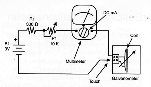
For precision in testing your galvanometer, place a common multimeter in parallel and see exactly the current it detects. Figure 9 shows how this can be done.
Galvanometer Test Circuit
B1 - 3 volts of power (2 AA cells and holder)
R1 - 330 Ω x 1/8-watt resistor (orange, orange, brown)
P1 - 10 k - linear potentiometer
Wires, solder, terminal strip, etc.
Exploring the Project
Experiments using the galvanometer can include some interesting projects. The experiments are divided in two groups: (1) using the galvanometer to detect the energy of alternative sources and (2) using the galvanometer as part of other projects.
Cross Themes
To present cross themes, some experiments use the galvanometer as detector of simple alternative sources of energy. Figure 10 shows two chemical alternative sources of energy.
Figure 10 (a) shows a cell made with a lemon or other citrus fruit. The electrodes are made of different materials such as copper for the positive, and zinc or aluminum for the negative pole.
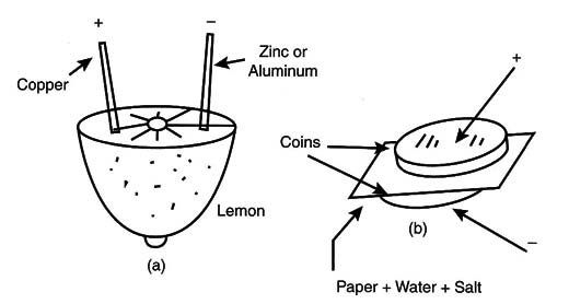
The voltage obtained from this cell is in the range from 0.3 to 1.0 volts depending on the metals used as electrodes.
Figure 3.5 .10 (b) shows a cell made with two coins. They must be of different metals (copper, aluminum, silver, etc.). A silver coin with an aluminum coin can create about 1.0 volts. The paper between the coins is wet with a salt solution. Touching the terminals of these cells to the terminals of the galvanometer, the needle will move and show the voltage of the cell.
Another energy source that can be used to test your galvanometer is a photocell such as the ones found in hand calculators. Touching the terminals of the galvanometer with the wires coming from the power source (photocell) and exposing the cell to light, the needle will move.
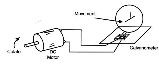
Finally, you can use a small motor to generate electric energy from movement. Figure 11 shows how the experiment must be done.
Increasing the Sensivity
Although the original version of the galvanometer is sensitive enough to detect currents of a few microamperes, the reader can increase the sensitivity by adding an electronic amplifier.
The circuit uses one transistor and can be mounted on & terminal strip. Figure 12 shows the schematic diagram of the amplifier.
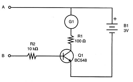
This transistor allows the galvanometer to be used as a sensitive continuity tester and even as & lie detector. A current of only a few microamperes (1 to 10 depending on the sensitivity of your galvanometer) is enough to move the needle. Figure 13 shows how to mount the circuit using a terminal strip.
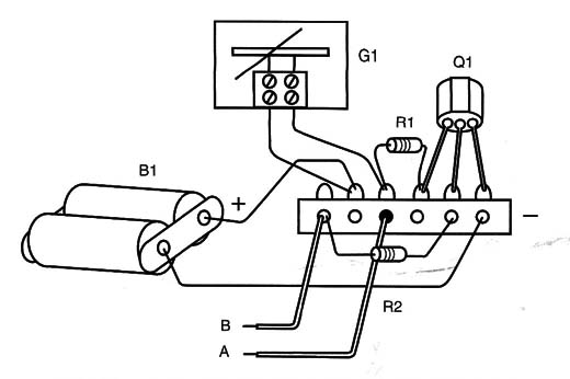
You can test the sensitivity of this project by connecting a 1 M potentiometer to the input. Test the circuit with the cursor of the potentiometer in different positions and determine the minimum resistance that causes the needle to move.
To use the galvanometer as a lie detector, you first need to know that the resistance of human skin changes when the person is under stress such as during an interrogation. The movement of the needle will detect small changes in the skin’s resistance.
To create a lie detector from a galvanometer, you will need to do the following. Make two electrodes by using two metal rods that can be held firmly in the hands of the suspect (the person being interrogated).
The person must be convinced that the circuit works, and he must keep constant pressure on the electrodes to keep the needle from moving. Figure 14 shows the galvanometer being used as a lie detector.
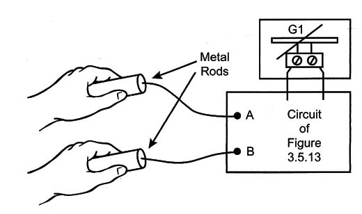
In the next section on additional circuit ideas, you will learn to build a high-gain amplifier that can increase the sensitivity of your lie detector.
When using the circuit as a component tester (continuity tester), you must attach probes to the input. If the component being tested has a low resistance (below 100 k typically), the needle will move. If not (for example, in an open circuit), the needle will rest (stop).
Amplifier
Q1 - BC548 or 2N2222 general-purpose negative-positive-negative (NPN) silicon transistor
R1 - 100 x 1/8-watt resistor (brown, black, brown)
R2 - 10 k x 1/8-watt resistor (brown, black, orange)
B1 - 3 volts of power (2 AA cells and holder)
G1 Galvanometer
Terminal strip, wires, solder, probes, etc.
Additional Circuits and Ideas
The basic galvanometer project can be changed, upgraded, or used for a different purpose. In this section, some variations on the galvanometer project are suggested.
Using a Compass
Figure 15 shows how a compass can be used to make a different version of the galvanometer. The coil uses enameled wire 30 to 32 AWG and is wound around a cardboard form With the dimensions shown in the figure.
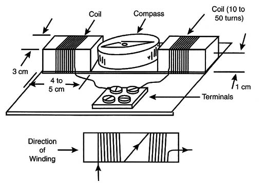
Notice that the second coil must continue in the same direction as the first coil. If not, the magnetic fields created by the two coils will cancel each other, and the galvanometer will not function.
A High-Gain Amplifier
A high-gain amplifier using two transistors can increase the sensitivity of the galvanometer up to 10,000 times. The circuit for this amplifier is shown in Figure 16. The transistors form a Darlington pair. The input resistance is very high, adding sensitivity to the circuit.
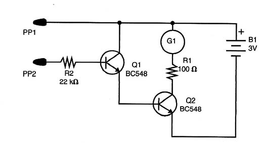
High-Gain Amplifier
Q1, Q2 - BC548 or 2N2222 general-purpose NPN silicon transistors
R1 - 100 ohm x 1/8-watt resistor (brown, black, brown)
R2 - 22 k x 1/8-watt resistor (red, red, orange)
B1 - 3 volts of power (2 AA cells and holder)
PP1, PP2 Probes
G1 - Galvanometer
Terminal strip or printed circuit board (PCB), wires solder, etc.
Figure 17 shows some circuits that can be used to increase the sensitivity of the galvanometer.
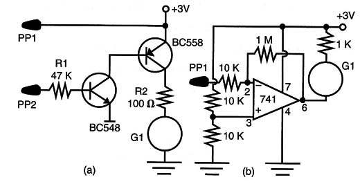
In Figure 17 (a), a circuit is using a complementary pair of transistors (NPN/positive-negative-posítive [PNP]). In Figure 17 (b), a circuit is using a Darlington transistor. In Figure 17 (c), the circuit uses an operational amplifier.
Light/Dark Sensor for Bio Energy
Light-dependent resistam (LDRs) are sensitive sensors for detecting light. They can be used to detect light and dark in experiments using the galvanometer as the indicator. A simple circuit used to detect light is shown in Figure 18.
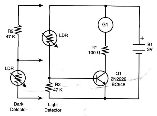
Insert the batteries in the cell holder and put the needle of the galvanometer in a position perpendicular to the plane of the coil. Use a flashlight to illuminate the LDR. The needle will then move, indicating the light detection by the sensor.
Light Detector
Q1 - BC548 or 2N2222 general-purpose NPN silicon transistor
LDR Common LDR
R1 - 100 ohm x 1/8-watt resistor (brown, black, brown)
R2 - 47 k ohmx 1/8-watt resistor (yellow, violet, orange)
B1 - 3 volts of power (2 AA cells and holder)
G1 - Galvanometer
Terminal strip, wires, solder, etc.


